


In-House Design Team
CLEANROOM SOLUTIONS’ in-house cleanroom Design team consists of specialist 2D (AutoCAD) and 3D (SolidWorks) Engineers; led by Directors with more than 100 years’ combined experience in the sector, their comprehensive design offering includes:

- General cleanroom arrangement layouts; structural, mechanical & electrical
- Process flow diagrams
- Elevations and sectional drawings
- HVAC P&ID, ductwork schematics, lighting layouts and wiring diagrams
- Pressure cascade diagrams
- Furniture & equipment layouts
- 3D models and animations
- Virtual reality facility walk-throughs

The Level of Design (LoD) and the software in which the complex cleanroom design is developed will depend on the complexity of the detail required to inform the design in accordance with the budget allocated. LoD may also progress alongside the development of the project to deliver further clarity at future stages.

Panel Layout: All cleanroom components fully dimensioned. Individual wall panels, glazing, single, double and rapid rise doors, return air columns and vents, wall-to-wall coving (if being used). Panel elevations included.
Ceiling Layout: Ceiling panels or grid, including points of suspension, LED lights, HEPA filters, smokeheads, CCTV cameras.
Cleanroom HVAC Layout: AHU(s), CRAC Unit(s), Fan Coil Unit(s) and/or Fan Filter Units detailed. Supply and return air ductwork in different colours with diameters shown, including heater batteries, VCDs and cleaning hatches. Filter size and positions, DOP ports and diffuser types outlined. Exhaust vents identified and dimensioned, power supplies shown for HVAC plant.
Electrical Layout: Distribution boards positioned, numbered and sized, 13-amp, 3-Ph and CAT6 sockets positioned, numbered and sized, containment runs identified, circuit logic detailed.
Lighting Layout: LEDs numbered relating to the lighting schedule in the MRS, Klik boxes positioned, wiring between LED and Kliks shown, emergency lights identified, PIR or switches shown.
Mechanical Layout: Compressed air, process gases, extraction, vacuum, purified water, town’s water, drainage. All pipework runs displayed with diameters, termination points detailed including fitting type and size. Plant identified and dimensioned.

Furniture & Equipment Layout: Process equipment identified and dimensioned. Changing room furniture and transfer equipment, workbenches and furniture.
Flow Layout: Pressures in each room, flow (personnel, material, air, equipment), supply volume at each supply grille, exhaust volume at each return air grille.
Door Layout: Singles, doubles, rapid rise doors, emergency break-through panels, interlock logic, control panels or buttons for automatic openers, emergency break glasses and traffic light indicators shown.

Mezzanine Layout: Supporting steelwork columns, mezzanine deck layout, staircases, pallet gates, edge protection, fire boarding.
3D Models: Provide a detailed and spatially aware render of the facility, they can be particularly helpful when designing tight void spaces, plotting process equipment and illuminating abstract concepts such as plenum designs and complex utility integrations. These can be converted into full animation videos that can be used for stakeholder engagement and developed into immersive virtual reality experiences utilising Oculus VR headsets.
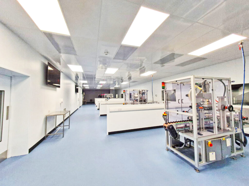
GUARDTECH CASE STUDY ISO5 DIAGNOSTICS REAGENT MANUFACTURING
Discover the design innovation, processes and challenges helped form this stunning 470sqm ISO5 manufacturing facility.

Guardtech Make an Enquiry
Got a question for the Cleanroom Solutions team? Maybe you have a rough idea of what you want and just need to flesh out the finer details? Click the button below to contact the team now for a rapid response to your enquiry.

Furniture & Equipment Guardware Cleanroom Hardware
Does your cleanroom require a stainless steel furniture fit-out? Maybe it’s some lab-grade Trespa gear you require? Laminar flow units? Biosafety cabinets? Transfer hatches? Whatever it is, Guardware Cleanroom Hardware will have the solution. Browse the range now.